We have written extensively about the importance of documentation in your WordPress projects, as well as in your plugins and themes. But documentation is not only about user manuals, code comments or online help. In cases where you have multiple clients and WordPress installations with different assets, you need a way to capture where all of this needs to be deployed. Enter UML and deployment diagrams!
What is UML?
UML or Unified Modelling Language, is a modelling language that helps software engineers design visual “blueprints” of systems, before beginning to write code. UML offers a set of notational diagrams that are versatile and can describe a lot of different aspects of a software system. There are notational diagrams that describe the system’s static aspect (such as architecture, components, relationships, operations, such as how the system behaves) as well as how the dynamic: how components interact and collaborate, and how the system’s internal state is changed.
The complete specification of UML is abysmally complex and while not all notations are useful, or relevant to WordPress projects, there are a few that can be quite extremely helpful. UML for that fact, got a bit misunderstood since it was abused by people that didn’t otherwise want to write a single line of code. They deferred any real work by designing large and complex diagrams which did not add any value.
What are deployment diagrams?
One of the many notational diagrams that UML offers is called the deployment diagram. It is surprisingly simple yet it offers much in terms of documenting project deliverables and showing in one diagram where every component is or where it needs to be deployed.
Deployment diagrams consist of nodes connected by communication paths. Nodes in this context are anything that can host software. They can either be a hardware device, like a server, or it can be an execution environment, a software which in itself can host another software, like a Virtual Machine, an application server, or a Docker container. Nodes are represented as 3D shaded boxes, while communication paths as simple straight lines. Execution environments are differentiated from nodes by placing labels inside guillemet symbols, for example, «VM-host-1».
Nodes can contain artifacts which are the physical software files themselves. These can be executables, binaries, JAR files, DLLs, HTML, configuration files, etc and are represented as labeled boxes. In the diagram, placing an artifact inside a node means that the artifact is deployed to that particular node. You can also use tagged values inside the nodes to show certain information (such as vendor, web server name, etc) by putting them inside curly braces. The communication paths between the nodes show how these nodes communicate. Usually, the paths are labeled with the communication protocol that is used (HTTP, SSH, NFS, etc). But there are no set standards. Let’s examine a simple example of how a deployment diagram can depict a WordPress project.
Try our Award-Winning WordPress Hosting today!

Deployment Diagrams in WordPress projects
It’s most likely that deployment diagrams won’t offer a lot of value if you use them in very small projects with few components. On the other hand, they can be a real life saver when it comes to large installations, particularly in media agencies with lots of clients and environments. The following diagram is an example of how a deployment diagram in a WordPress project could be depicted:
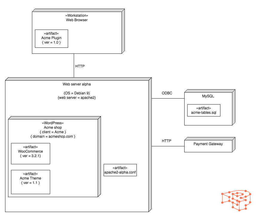
There are four nodes in this diagram. The main one labeled as “Web server alpha”, containing an execution environment labeled “WordPress” that hosts all the assets for Acme shop. Additionally, we used relevant tagged values where it made sense. It is really that simple!
The manner by which you will use the notation is up to you and it will depend on the architecture of your WordPress project. For example, you might have a node that hosts multiple execution environments that in turn host individual WordPress installations for clients. Ensure that artifacts are placed correctly, the node hierarchy reflects the actual physical system layout, and the communication paths are connected and labeled correctly as well. In case you aren’t using specific filenames for the artifacts, make sure that they can be identified and are not ambiguous.
UML Tools and Resources
Since the development of UML in the mid-’90s, you can find a plethora of UML drawing tools for all platforms. There are also a few online such as Gliffy, Creately, Draw.io and UMLetino. If you use IDEs to do your development work there are UML plugins for Netbeans and Eclipse respectively.
Lastly, if you want to get started with UML and wish to explore further but don’t have time to pore over reams of arcane specs and minutiae, get yourself a copy of Martin Fowler’s UML Distilled. It is excellently written, the book manages to present you succinctly with everything you need in less than 200 pages!
Start Your 14 Day Free Trial
Try our award winning WordPress Hosting!